
Bootstrapping (BT) in programming is an antonym for starting from scratch. BT generates the boilerplate parts of the Structural Text (ST) code, so a programmer may skip the time-consuming and boring setup and focus on application-specific parts.
BT in PLC Control Software development has a well-defined objective - to translate the control data already set by the process design to the ST program.
To perform this task crenger.com uses the ST code generator. It generates the boilerplate code using ST instructions and a set of code templates.
A template defines the style of the ST variable tagging and contains instructions on how to comment on the variable to the programmer. Rich commenting is one of the most powerful things about the BT generator. Comments and tags are the backlinks to the process side. They make code readable.
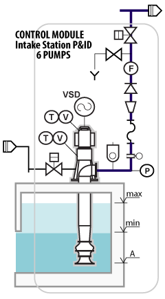
The previous article "PLC Control Software Architecture" explains how the plant is subdivided into control modules (CM) and which structures may be used to describe the CM content auto-cropped from the P&ID. The same set of the BT templates is applied to every CM of the plant (well over 100 times!).
The CM program template includes two distinct parts - the declaration and initialization of all the variables used in the program and the control logic code. This article discusses the first part. It covers the following categories.
- the IO device hardware addresses (global)
- the IO device variables (local)
- the IO device event variables (local)
- the CM-emitted event variables (global)
These entries form the PLC database. It should contain enough information to cover all the PLC tasks starting from control logic, to HMI design, the alarm rationalization, and the plant status messaging.
Two outcomes of the plant auto-wiring technology in action are partitioning the IO devices between PLCs or IO drops and auto-linking them to PLC IO modules (to get the device signal physical addresses). Below is the PLC rack viewer bundled with PlantDesigner software.
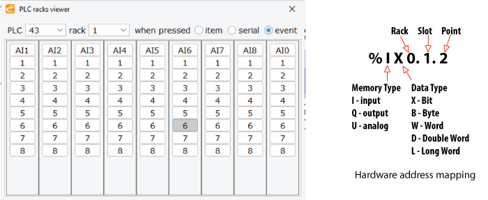
An acceptable format for the address variable on a typical PLC system is as follows: D12R3S4P5, where D12 is drop 12, R3 is rack 3, S4 is slot 4, and P5 is point 5. The said variable is mapped to the physical address having the designation explained by the figure on the right side.
Below is an excerpt from an auto-generated list of hardware address variables declaration. The entry comment is critical as it is a link to the process side of the plant. The full list includes 2000 - 6000 entries ready to be copied to the PLC control program text.
Variable declarations for IO devices and events (Points 2, 3, and 4 of the above list) are partitioned between programs describing CM. Here the ST function block is not a choice as the declarations are too lengthy. This point is illustrated by the following example of boilerplate PROGRAM describing the intake pump P&ID shown above. As the station contains 6 pumps, the same program with different tags and IDs is auto-generated 6 times.
As seen an event IO address is mapped to a hardware address described above or a software one starting with letters F of A followed by an event ID. This address is merely a memory location that is internally mapped to a particular I/O module. As the nomenclature for memory location varies with the manufacturer of the control system, introducing universal software addresses makes the ST code portable.
All alarms contain some value - a threshold to witch the measured value is compared. If it is below or above the alarm's value the alarm is activated.
In desalination megaprojects only the ST variables' declaration and initialization add over 15000 lines of code.