
Design deviations (DDs) are a class of deviations identified during construction and commissioning. They describe the difference between intent, as described in the technical specifications and drawings, and what is observed on site. Typical examples of DD are given below.
- opposite direction of the flow or an order of valves installed in series
- blocked access to manual valves or instrument displays
- not visible nameplates or barcodes
- opposite direction of the motor rotation
- missing parts in assembly (predominantly of auxiliary systems)
- loosely installed parts
- lubrication missed
As well DD covers cases when some equipment has been removed to permit testing, cleaning, or leak testing.
As DDs are unplanned, their handling always affects project schedule and resource planning. In that respect, DDs are usually prioritized as blocking, non-blocking, non-functional, and optional.
Blockers shall be rectified immediately after reporting, non-blockers may be delayed until the plant handover. The non-functional DD affects neither the system functionality nor O&M; it only requires adding “as-made” remarks to documentation. DD is tagged as optional when it improves operation or safety. The latter triggers the project engineering change procedure.
The DD management (DDM) is a collaborative process of its registry, finding remediation and estimating its impact on the project progress, assigning to team members, rectification, re-checking, and approval.
In conventional management, DDM is reduced to maintaining a punch list – an Excel file listing DDs. Its updating is time-consuming and error-prone as the input is manually collected from stakeholders. Moreover, there is no possibility to link the punch list entry to documentation supporting DD and its location on the P&ID or layout, which makes DD verification difficult.
Digital DDM developed by crenger.com resolves the mentioned problems by implementing the following features.
- Online DD submission
- Centralized data management
- Direct access to P&IDs, layout, and design data,
- Real-time progress tracking
- Automated role-based issue assignment
- Automated notifications and workflows
- Automated reporting and analytics
- Automated location tagging
- Transparency in issue resolution
- Rating subcontractors on issues and responsiveness
The DDM user interface is shown below. It contains three parts – Main, Object Selector, and Image Editor.
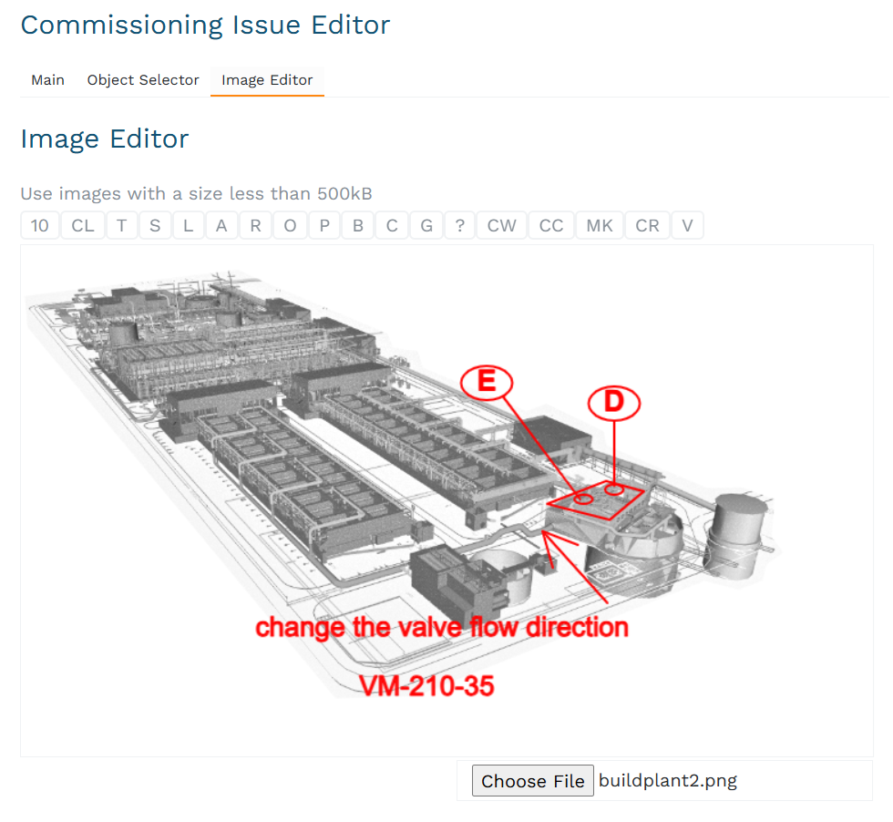
After DD is described, it should be linked to the plant object – the system, P&ID, the group of P&ID items, the item, alarm, interlock, or control loop. Additionally, the image with instructions and clarifications may be added to DD using Image Editor. DD has been submitted, the project workflow is being updated.