

Civil and structural design (CSD) is started after the plant mechanical design and the 3D model are completed. Its deliverables are data on buildings hosting the process equipment and structures on which the equipment and piping rest. The construction budget and schedule are part of CSD as well.
In conventional project management, CSD is skipped during bidding as the plant's 3D model is unavailable. Without it, the civil and structural works (CSW) are classified as the plant balance and budgeted as a percentage of the process capital costs.
In desalination megaprojects the CSW contribution to the project budget may be well over 30%. This figure is high enough and necessitates returning from the ball-park estimation to a detailed one based on CSD output. It will decrease the project budget contingency and raise chances for success.
Adding CSD to FEED (Front End Engineering and Design) - the core of the megaproject bid - without building the 3D model became possible only after crenger.com developed the framework for the plant layout auto-generation. It is outlined in the previous article.
Such a none-3D model approach is not seamless, it leads to some input data loss. How can it be mitigated during bidding?
The next problem is the data interpretation. In simpler terms, it is an extraction of data requested by CSD from the bulk of the FEED data. This task has never been on the process engineer's agenda.
Finally, CSD is time-consuming as it is usually outsourced. Without automation, it can't be squeezed into the project bidding timeline.
The first step in adding CSD to FEED is identifying and collecting all available data bits needed to start CSD in a single batch with a format native to CSD. (Native formats are discussed in "Information Interoperability".)
What data is vital to CSD? To answer this question, we need to look at the CSD output. It may be broken down into primary data (input) and derived data.
The CSD core output invariably includes the following plans.
- Foundation location
- Underground structures
- Underground drainage
- Roads
The foundation location plan is a specialized architectural drawing that depicts the exact location of equipment, platforms, pipe racks, buildings, and structural concrete supports (mostly for pipelines) within a designated site. It is accompanied by the foundation specification addressing the foundation type, footing dimensions, reinforcement details, etc.
Here the basic input is the equipment weights, locations, and footprints. FEED does not contain this data. The framework for collecting and predicting it is discussed elsewhere.
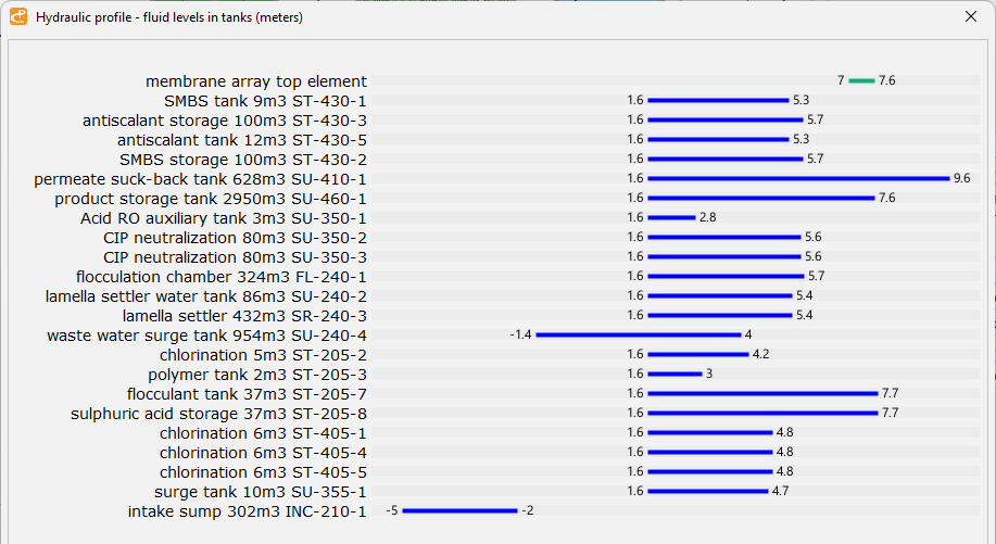
The underground structures plan refers to constructions built beneath the Earth's surface, either partially or entirely. The intake station sump, the seawater intake tunnel, and the brine discharge surge sump are examples of underground structures.
This plan may be completely designed using the FEED data regarding the plant's reservoirs' sizing. The image below shows the summary of the maximum and minimum water levels in all reservoirs of the SAMPLE plant bundled with PlantDesigner software. As seen, the plant has only 2 underground structures.
The plant's hydraulic profile
The underground drainage system is intended to prevent equipment flooding resulting from sudden bursts of piping, RO pressure vessels, pressure relief valves, emergency drainage, or fluid tank overflow - a safeguard against the plant's abnormal operation. Safety concerns make this system a crucial component of a plant. Its design is heavily tested during commissioning and the plant's first start.
The underground drainage plan should specify all the drain points and how they are connected into a network of pipes, channels, inspection chambers, manholes, and an outflow point at which water leaves the plant site. Normally, FEED includes a simplified version of this plan where construction details are omitted. It is discussed in "Underground Drainage Design Automation".
The roads plan is the simplest of all as the road routes may be directly extracted from the plant layout.