
In practical terms, a controller is a device that makes the system transition between stable states safe and within the design limits. Better controllers make it faster.
Today the controller design is boiled down to tuning a commercial PID controller using different strategies. Interestingly, all of them disregard the process model and focus on the process disturbance-response analysis. The latter requires a deep sense of process dynamics which normally comes with years of experience. Such experts - control engineers - are expensive and in short supply in any industry.
Delegating the controller tuning tasks to the instrumentation and control engineer (which is 95% instrumentation and 5% control) is not a choice in megaprojects for the following reasons.
- Onsite tuning of the PID controller requires deactivating some alarms (to test instability bounds). Forgetting to re-activate them leads to equipment damage. In my career, I witnessed two such accidents related to pumps and reverse osmosis membranes. In each case, losses were well over US$200 thousand.
- It is difficult to isolate the controlled process from the rest of the plant, so interpretation of the process response is unreliable.
- Unlike the control engineer, the I&C one starts with zero knowledge about the process type. It makes the controller optimization unfeasible.
To resolve the challenge deeper insight into the process is needed. It is readily offered by a digital twin (DT) driven by numerical process modeling.
DT may be considered a stable state generator and a supervisor of the PID controller.
Its algorithm now has the following form.
CV = CV0 + Kp*E + (integral & derivative terms)
where CV is a control value, CV0 is the value generated by DT, Kp - proportional gain, and E - error after CV0 set.
In the case of DT the PID tuning stops being a guesswork. This point may be illustrated by the following example.
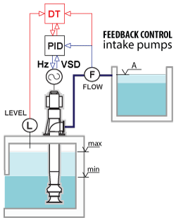 The water level of the intake pumping station shown above varies with time. To maintain the constant output of the pump its motor is equipped with variable frequency drive - the final control element of the feedback control loop with the P controller. A decrease in the water level causes a drop in the pump output. To restore its value to a set point the VSD frequency Hz shall be increased.
The described process is part of the standard DT offered by crenger.com for the plant operation and maintenance simulation. The DT runs may be watched on the website.
DT solves the equation Hz = F(flow, level) numerically using the pump performance curves. The found controlled value is not transmitted directly to Vsd. Instead, it is fed to the controller for possible adjustment. For this task proportional gain may be replaced with dHz/dFlow derivative numerically calculated by DT. In other words, DT is a way of the PID controller tuning automation. (Advanced versions of DT use the plant data for self-tuning. They replace the PID controllers entirely.)
As DT takes most of the work off the PID controller (and an I&C engineer) many options that come with the commercial controllers become redundant. These options make controllers non-portable across the PLC systems.
A simple portable controller sufficient for working with DT may be coded in Structured Text (ST). How simple can it be? As follows from the table below (representing metrics obtained from three desalination megaplants) pure gain processes dominate. They are considered the lowest in complexity.
| Control | Type | % |
|---|---|---|
| flow ratio | pure gain process | 54 |
| flow | pure gain process | 27 |
| level | capacity process | 10 |
| level-to-flow ratio | pure gain process | 5 |
| pressure | pure gain process | 4 |
The ST code for a basic version of the PID controller is given below.
The first step in automating the controller design is the collection of data. As this assignment becomes the responsibility of the process engineer, the control design framework has been added to the PlantDesigner software. Its user interface is shown below.
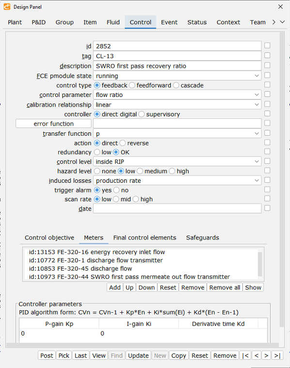
A P&ID item is added to a control loop by a button click. The data collected cover all the types recommended by the ISA-5.06.01-2007 "Functional Requirements Documentation for Control Software Applications" standard. Some entries are auto-generated at a later stage when the control design is completed.
The ST data structure corresponding to the above interface is shown below. It is used for the automatic declaration and initialization of the control loop's variables in the PLC program.