

Engineering logic is an extension of control one to specific domains of knowledge. It handles monitoring and control points where engineering laws wrapped into Math functions are used.
Examples are the remaining fluid volume in the tank, the pump efficiency, the flow rate through the orifice, the reverse osmosis recovery ratio, or the total energy consumption.
Functions are used in alarms, control loops, and systems operation monitoring. They should be selected, customized, validated, annotated, and tagged before handing over to the control engineer.
All the mentioned tasks are far from trivial: they require deeper experience and extra time. So they are often postponed until procurement is completed. This practice increases immeasurably the risk of possible misses in the process design.
To move these tasks to their logical place crenger.com has automated it. The pivot of automation is the Transfer Function Object (TF) outlined in "Any Data Acquisition Principles". TF allows the user to enter the Excel-formatted function and check its output. TF has "live" variables - P&ID item attributes. When they change the TF output changes. As an object, it can be stored in the database or even in a cloud as TF solves the challenge of non-unique identifiers blocking the cloud IT advances.
Standard TFs are auto-generated from P&ID. They cover energy and mass balances and the pumps and membranes operation. Below is a snapshot of a web application showing the function list for the plant data acquisition.
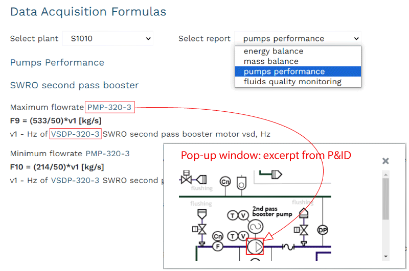
In this list all the tags are hyperlinked; when clicked a window with an excerpt from the P&ID pops up.
The only reason why some requested function is not generated for the P&ID item is a lack of proper instrumentation. It is a red flag for a process engineer to upgrade the P&ID.
The interface shown below is used for user-defined TFs. It throws light on the TF principle structure. Besides the function expression, it contains a fault condition used to turn TF into an alarm, the usage type, and a destination. The former describes the function's primary intention, while the latter - the consumers of its output: database, HMI display, messaging, web, or the O&M report.
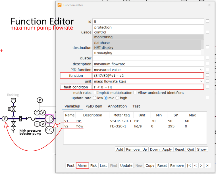
The above snapshot of the function editor shows the function containing two items. The first one - (347/50)*v1 - is auto-generated. It calculates the maximum flow rate of the pump as a function of the v1 variable - the input to the variable frequency drive. The v2 variable is measured flow rate. The obvious question is where the 347 and 50 figures come from. 50 stands for the voltage frequency read out from the plant specification while 347 is the maximum flow rate of the pump got from the pump performance curves rebuilt by crenger.com for 50 HZ using the in-built pump search engine.
It means that TF has access to the plant database and knows how to read P&ID and equipment documentation. The next level of TF development is replacing the hardwired function expression for digital micro-twin driven by machine learning algorithms.
To export TF to Structured Text program the function expressions shall be converted from Excel style to the ST one. It is the task of the function converter. Here is an example.
v1*sqrt(v2)/v3^0.75 -> v1*SQRT(v2)/EXPT(v3,0.75)
As any TF has an internal state (described by usage, destination, description, etc.), it is best represented by the ST function block.
On average, the generated number of the function blocks is in the range of 80 - 120.