
Michelangelo is quoted as saying "Trifles make perfection, and perfection is no trifle". Here we'll talk about engineering trifles that pave the road to the plant perfect design.
Intake Pumping Station
 Rotating band screen. Most important points are materials selection, corrosion protection, whether to specify "pull-out" design, spinning reserve capacity, and the size of the mesh. Point to remember is that the reliability of the screen depends upon the depth of the intake sump; not all manufacturers have enough experience with the lengths above 15 m.
Common bad practice is gross oversizing and specifying ample standby capacities .
Intake pump. Horizontal axially split pumps are 3 times less expensive(!) than the vertical turbine pumps. Besides, the former require less space; their performance is in lesser degree affected by the inlet stream hydraulics. The horizontal pump reliability is at least 2 times as high as that of the vertical one.
The only advantage of the vertical pump is zero risk of flooding and lower noise emission. Application of double decks and the pump room partitioning reliably solves the first problem.
The intake pumping station capacity shall be higher than the aggregate feed flowrate to the SWRO trains by 5-6% if multimedia filtration is used, and by 10% for ultrafiltration. Energy recovery adds another 2 - 3%. If DAF or lamella settlers are used in the pretreatment, the output shall be increased by 1.5 - 2.0%.
The pump motors require good ventilation as higher temperatures affect the motor capacity. As this is not always the case, the motor capacity shall be increased by at least 5%.
In selecting the pump maximum head (and the motor capacity accordingly) the minimum sea water level, design maximum fouling of the intake piping, and the maximum plant output occurrences shall be considered. Of primary importance is the height of the pump baseplate over the sea water highest level. During power supply interruption the flooding of the intake sump starts.
As a rule of thumb, each 1000 meters of the intake piping raise the water level by 1.2-1.5 m (above zero level). If, for example, the intake pipe is 3000 meters long, the water rise in the intake after power interruption may be not less than 3.6 meters. Long-distance discharge piping shall be equipped with the anti-water-hammer devices, the simplest of all is the air tank installed at the station and connected to the discharge manifold at the dead end. 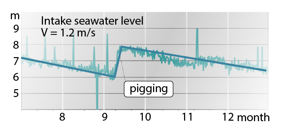
Pretreatment
Pretreatment will likely continue to be the most challenging part of the plant design. Standard pretreatment configurations are as follows.
- DMF
- DAF + DMF
- LC + DMF
- DMF + DMF
- DAF + DMF + DMF
- UF
- DAF + UF
- DMF + UF
- LC + DMF + UF
- DAF + DMF + UF
Here DMF is the Dual Media Filter of the gravity or the pressure type.
For each geolocation area there exists optimal pretreatment configuration. For example, 4 plants is Israel use Option 1, and one plant – Option 6 mostly due to the available area limitations. (UF requires 2 times less footprint area)
Special attention shall be given to the comparison of DAF and lamella settler. The former features low capital costs, small footprint and relatively good efficiency especially considering first two advantages. Although the lamella settler is bulky and requires maintenance, it is not an alternative to DAF, which does not handle high turbidity (or TSS).
Flocculation. Any of the above-mentioned pretreatment configuration requires chemical dosing to improve and speed up the filtration/sedimentation processes. Better to avoid expensive static mixers and inject the reagent directly into the pump suction. If the static mixer is unavoidable, its diameter shall be at least 2 sizes less the interconnecting piping. Extra injection nozzles shall be provided.
If an agitator is used for mixing, it is critical to correctly connect the inlets and outlets of the fast mixing chambers and slow mixing ones to avoid the stagnation zones. Slow mixing chamber volume shall provide 6 - 9 minutes of retention time.
Lamella Settler. The most popular type in desalination plants is the lamella settler combined with the rotating bottom scraper. Both are nicely fit if the filtration velocity does not deviate substantially from 15 – 20 m3/h/m2 (maximum settling velocity being about 0.35 mm/sec).
DAF System. Efficiency of the DAF systems critically depends upon the design goodness of the air saturation vessel. Common mistake here is selection of the horizontal vessels, which practically do not do their job as it is difficult to provide good contact times for air-water interface. Always start from vertical vessel with raschig rings filling at least 2 meters high.
As the air compressor is of standards design, the maximum pressure in the system may be maintained at 10 Barg. This value shall be the design one for the water piping and the DAF circulation pump selection.
Sometimes DAF is installed after the lamella settler (with the clarification rate of 15 - 20 m3/h/m2). Flocculation objectives for DAF and sedimentation are different because of the reverse principles. Sedimentation is slow process that requires larger flocs for gravity settling while DAF is 100 times faster; it needs smaller flocs of 10-30 µm and may be designed for clarification rates far above 50 m3/h/m2.
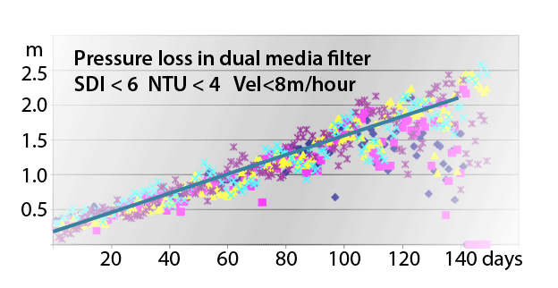
Multimedia Filters. Despite the simplicity of the gravity multimedia filter construction and the operation principles, their engineering requires experience just to avoid the following common problems (large SWRO plant commissioned in 2013).
- Low backwash quality due to incorrectly selected geometry of the filter
- High loss of the filtration materials (much above 2% per annum)
- High biofouling and algae growth rate in the open backwash tank
- Below-design flowrate of the backwash water to the remotest filters
Experience matters most in selecting the filtration material type and the filtration velocity, which varies in the range 7 – 15 m/h in the existing plants worldwide.
In selecting the filtration material layer height the following is recommended.
| Filtration material | Height (nozzles), mm | Height (underdrain), mm |
|---|---|---|
| Gravel | 200 | 0 |
| Sand | 600-800 | 400-600 |
| Anthracite | 700-900 | 600-800 |
The silica sand size tends to be larger in bigger plants. Instead of about 0.6 mm it is common to specify 0.9 - 1.1 mm as in a batch actual sand sizes vary from 1.3 to 0.5. About 30% may be below 0.7 - 0.8 mm.
What really improves filtration quality is medium layers above the sand layer. Their optimization may increase the filtration velocity by a factor of 1.3 - 1.5.
Transition to the pressurized filters amplifies the criticality of the above-mentioned problems. At the same time these filters have much higher quality of works and lower lead times. The biggest advantage of the pressurized filters is the possibility to install the high pressure feed pump after the filters without the booster pump and the clear water tank. Finally the pressurized filters are more suitable for the backwashing with the brine discharged from the SWRO trains.
The design backwash velocity for any type of multi-media filter is 50 m/hr, accompanies by air scouring at 30-60 m/hr.
Below is an example of backwashing cycle
| Step | Time, min | Flowrate, m3h | Volume, m3 |
|---|---|---|---|
| Draining | 10 | ||
| Air scouring | 8 | 6400 | |
| Combined air + water | 5 | 1200 | 100 |
| Washing | 1.2 | 6400 | 120 |
| Settling | 2 | ||
| Draining | 6 | ||
| Washing | 2.4 | 6400 | 240 |
| Settling | 2 | ||
| Draining | 8 | ||
| Slow washing | 9 | 1200 | 180 |
| Filling up | 5.4 | 1200 | 270 |
| Total | 60 | 910 |
The step times do not include the valve opening/closing times.
Clear Water Tank (if applicable). This is a surge tank intended to smooth the filters operation during the backwashing, to provide some retention time during chlorination, and synchronize pretreatment and the SWRO trains operation. This tank geometry shall be a reasonable compromise between the two factors working in opposite directions: the filter rows on the one side, and the operated in parallel pumps, on the other side. The clear water piping containing the flowmeters shall be always flooded.
Backwash Tank & Pump (if applicable). The backwash tank volume shall be enough to provide 2 consecutive backwash cycles during stormy weather in winter. With thoughtful selection of the pump curve there is no need in the backwash tank filling control. Backwash Air Blower To not oversize the blower, its nominal capacity (Nm3/h) shall be defined based on the minimum water temperature and the pressure of 40 kPa above the atmospheric one. The noise level shall clearly stated.
Cartridge Filter. Cartridge filters are intended to safeguard the RO membranes against spikes in SDI due to filters unexpected outage. Plan the cartridge replacement at the pressure loss of 1.5 Barg. Prefer horizontal configuration to the vertical one. The former allows more options for the nozzles orientation and better matching to the linked equipment. The cartridge filter station including many filter vessels installed in parallel is not always the best approach. You may relax the requirements for filters installed after ultrafiltration guaranteeing lower SDI values than DMF. 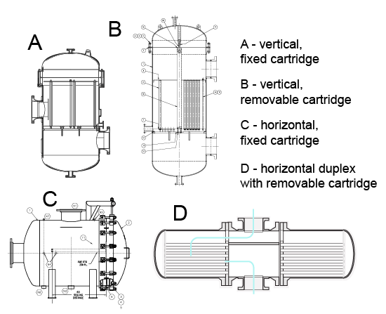
Reverse Osmosis
Feed Booster Pump & High Pressure Pump. Being equipped with VFD , this pump shall provide variable head in the range 50 – 100%. This range shall be matched to the feed pressure variation before the SWRO membranes, which in most cases is 6 - 10 Bars. High efficiency and low NPSHr are the main criteria of the pump selection. Be conservative in selecting high pressure pump; specify API-compatible variant allowing high loads and moments on the nozzles. Prefer oil-lubrication to grease one; forced lubrication to natural. Remember that SWRO plant design is all about pretreatment and the start/stop sequences for high pressure pump. The latter shall guarantee (!) the feed pressure variation not more than 0.7 Bar/sec during transients not to lose the mechanical guarantee of the membrane manufacturers. These sequences, their pros and cons shall be fully discussed with the client. Especially if the plant is planned to use for power peaks shaving or its operation is tied to the electricity tariffs or if the plant is powered by solar energy.
Energy Recovery
Energy recovery devices are not ideal; each one has its cons and pros. Comparison of the devices shall take into account the following factors.
- Energy recovery efficiency
- Mixing between feed and brine streams
- Feed water losses
- Reliability
- Noise
- Sensitivity to fluid impurities
- Corrosion resistance
- Interconnecting piping costs
- Ease of modularization
- Maintenance costs
- Service life
- NPSHr and pressure differential at the low-pressure side
There is no absolute winner. For example, the ERI device features remarkable reliability on the one hand, and high noise, low unit capacity and high volumetric mixing on the other hand. DWEER shows maximum efficiency paired with lowest reliability due to cyclic fatigue of the materials. Turbocharger is the only choice if the feed salinity changes more than 20 - 30%. Pelton turbines work best for cases where the output follows the daily demand.
RO Passes
For quick estimate of the number of RO passes the following rule of thumb may be used.
- At product TDS ≥ 500 ppm and no low Boron requirements single SWRO pass is enough.
- At product TDS ≤ 450 ppm and low Boron requirement extra 1 - 3 BWRO passes shall be added.
- At product TDS ≤ 300 the SWRO permeate shall be split into the front-end stream (with TDS < 100) and the rear-end one additionally treated by BWRO.
RO Recovery Ratio
For seawater of TDS = 40000 ppm the SWRO stage recovery ratio control shall be within 42 – 50%. For BWRO stages the recovery ratios are generally over 85%.
RO Membrane Projections
SWRO and BWRO membrane projections shall define the following process envelope.
- Maximum salinity, minimum temperature
- Maximum temperature, minimum salinity
- Maximum membrane fouling, maximum product output
- Minimum membrane fouling, minimum product output
In fact, this envelope is the guaranteed performance of the plant, it is not useful for the plant equipment selection. The latter shall be done based on the math model of the plant run at least 365 x 24 times to perform the energy consumption integration over the time of the year.
The minimum fouling factor values reflect the contractor experience in O&M and the accuracy of the input data. For SWRO and BWRO passes fouling factors shall be taken not less than 0.7 and 0.8.
Every membrane manufacturer has its own safety factors for projection output parameters: feed pressure to membranes, permeate quality, final ions concentration, and pressure losses.
| Nu | Category | Value |
| 1 | Seawater pressure, kPa | 6800 |
| 2 | Seawater temperature, oC | 25 |
| 3 | Seawater salinity, kg/kg | 0.04 |
| 4 | Seawater flowrate, kg/s | 641 |
| 5 | Permeate pressure, kPa | 160 |
| 6 | Number of RO modules in vessel | 8 |
| 7 | Membranes vessels number | 288 |
| 8 | Fouling factor | 0.73 |
| 9 | Head/rear permeate flowrate ratio | 0.3 |
| 10 | Membrane manufacturer | TORAY |
| 11 | Recovery | 0.4601 |
| 12 | Head permeate salinity kg/kg | 0.00016 |
| 13 | Rear permeate salinity kg/kg | 0.00042 |
| 14 | Permeate maximum flux, kg/sq.m*h | 22.03 (first membrane) |
| 15 | Permeate flowrate, kg/s | 294 |
| 16 | Brine pressure kPa | 6706 |
| 17 | Brine flowrate kg/s | 346 |
| 18 | Brine salinity kg/kg | 0.0738 |
| 19 | Membranes stack cost, $USA | 952000 |
Permeate Re-mineralization
Permeate after membranes shall be low pH, alkalinity, hardness, LSI, and free chlorine contents. These parameters shall be tailored to the client's product specification. For example, the pH and LSI adjustments are more important for product intended for process.
Dissolution of Calcium Carbonate augmented by Carbon Dioxide or Sulfuric Acid is in frequent use due to lower costs and reagents availability (Table 1). Modelling of such processes may be done with a number of commercial software packages like Water Conditioning and Scaling Control and Stasoft.
| Process | Pros & Cons |
|---|---|
| Ca(OH)2+2CO2 = Ca(HCO3)2 | high turbidity, high cost of calcium hydroxide |
| CO2+CaCO3+H2O = Ca(HCO3)2 | low turbidity, low cost of calcium carbonate, preferred in cases of high alkalinity |
| 2CaCO3+H2SO4 = CaSO4+Ca(HCO3)2 followed by Ca(HCO3)2+H2SO4 = CaSO4+2CO2+H2O | low turbidity, low cost of calcium carbonate |
Adding Ca(OH)2 – Calcium Hydroxide as lime milk may increase the product turbidity unless clarifiers are used.
The example of limestone reactor backwasing procedure is given below.
| Step | Time, min | Flowrate, m3h | Volume, m3 |
|---|---|---|---|
| Draining | 6 | ||
| Air scouring | 3 | 1800 | |
| Combined air + water | 5 | 300 | 25 |
| Washing | 10 | 900 | 150 |
| Draining | 5 | ||
| Washing | 5 | 1800 | 300 |
| Draining | 5 | ||
| Rinsing | 60 | 900 | |