
Plant layout is the first document every project stakeholder wants to see. Its design requires expertise, is time-consuming, and holds the first place in engineering error rates. Below is an overview of how crenger.com turned this project risk into a 10-minute journey.
Strictly speaking, the plant layout is a synonym of the plant 3D mechanical model. It, in turn, is an implementation of the plant layout guidelines (LG) produced by process engineering at the same time as Process Guidelines (PG) focused on equipment sizing.
While LG is a starting point for mechanical and civil engineering, PG is for the P&ID development. The objective of LG is to configure the main equipment arrangements and anchor them to the plant site.
While LG is prepared in 2 - 4 weeks, a 3D model requires 3 - 6 months and certified information from OEMs (which is unavailable at the project commencement ). Naturally, LG ( not the 3D model) is used for project bidding, presentation to the client, quotation requests for works, and even control design and engineering.
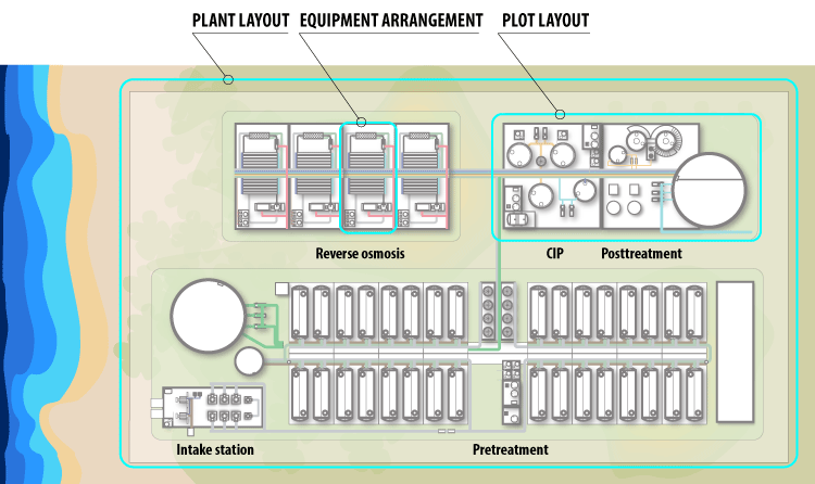
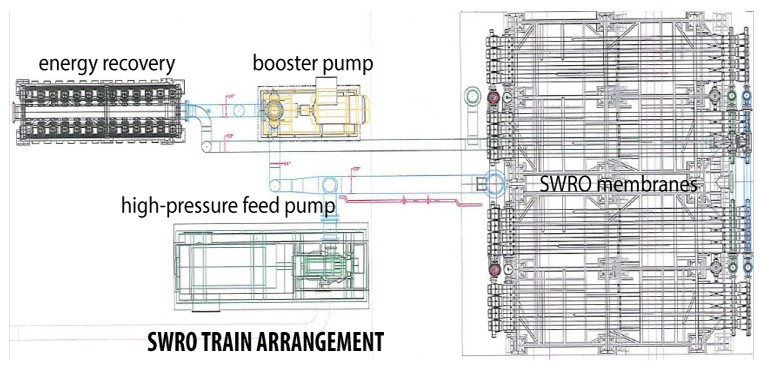
As seen from the figure above the plant layout is an arrangement of plots oriented along the process flow direction. A plot is composed of several equipment arrangements. Any arrangement may be represented by a single row (like reverse osmosis trains) or multiple rows and columns (pressure filters of pretreatment) of a drawn-to-scale top view of an equipment piece. In practice, it is cropped from the existing 3D model made previously. An example of such an excerpt is shown below.
The number of identical equipment pieces and their proximity to other pieces representing a different process is defined by the process sizing and flow given in PG.
What links PG to LG is a library of the preconfigured equipment arrangements. Each one maps the equipment datasheet to its image dimensions. Below are samples of the arrangement images from such a library bundled with PlantDesigner software. They are stripped of any unnecessary details: what matters is shape, dimensions, and tie-in points.
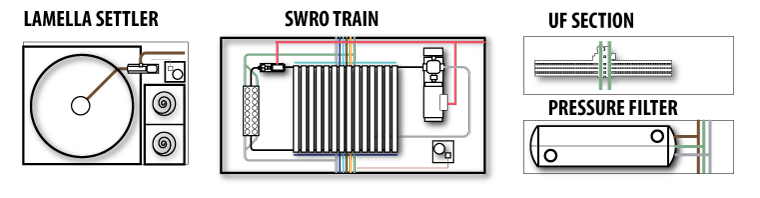
Internally, the arrangement object is linked to an engineering calculator producing instructions on how to transform the original image, and the image processing utility. The calculator has access to the PG data.
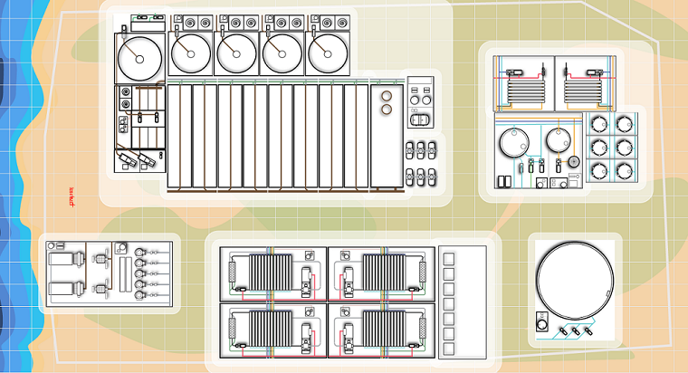
With arrangement layouts being fully automated, the plant layout creation boils down to the plot assembling from the puzzle pieces - the equipment arrangements. Normally, this task takes less than 10 minutes - over 200 times faster than the conventional way. Below is a sample of the pre-generated layout.
Fast generation of the layout options by PlantDesigner opens up the door to the application of AI-driven generative design for LG optimization. It will be discussed elsewhere.