
System functional testing (SFT) relates to the final stage of the “design-build-validate” paradigm of the infrastructure project execution. The primary purpose of SFT is to validate the design intent (DI).
Any formal document does not fully capture DI as it consolidates the project requirements, quality control tasks (QC), performance optimization, and new knowledge extraction. The last two tasks may relate to the technology development spanning several projects.
DI addresses the following validation priorities set during the plant design and engineering.
- Normal start-up/shut-down sequence validation
- Systems controllability and observability
- Control and safety logic and the PLC program debugging
- Warranted system performances
- System designs match to a probable range of operation loads and patterns
- Abnormal operation patterns when some systems are not healthy or down
- Operation resilience to control malfunction or human errors
SFT starts after all the plant systems have been assembled and checked mechanically in no particular order. Mechanical completion (MC) includes the process, power supply, and control interfaces of a plant.
SFT is followed by integrated site acceptance testing (ISAT) benchmarking the plant performance, reliability, and operators' training adequacy.
Unlike MC, SFT is sequential. It should be executed in a strict order of systems energizing and pressurizing. The SFT sequencing is a missing chapter from the book of conventional engineering.
To figure out the SFT sequence the full plant topology should be available. Topology is a generic term describing node connections in a network. The node may represent an equipment piece or a system. While in industrial control network topology is interchangeable with network layout or architecture, in our case the plant topology substantially differs from the plant layout.
The plant topology is a superposition of three topology classes – the process flow diagram (PFD), the one-line diagram (OLED), and the control architecture (CA). The PFD connects process systems, OLED - electrical panels, boards, MCCs, and switchgear, and CA – junction boxes, marshaling and PLC cabinets.
PFD represents the plant as a uni-directional graph of interrelated systems. It contains two types of nodes corresponding to auxiliary-process systems and main-process ones. A system pointing to another system is called the support one. Power supply and control systems are the support ones too. The chain of the PFD main systems shall not contain any auxiliary system in between. Auxiliary systems may form a chain producing some by-product (like sludge dewatering or brine valorization).
Generally, SFT should proceed from the support system level and the auxiliary process level to the main process one. Auto-generated by crenger.com the plant topology is described by the uni-directional graph showing the order of the nodes activation.
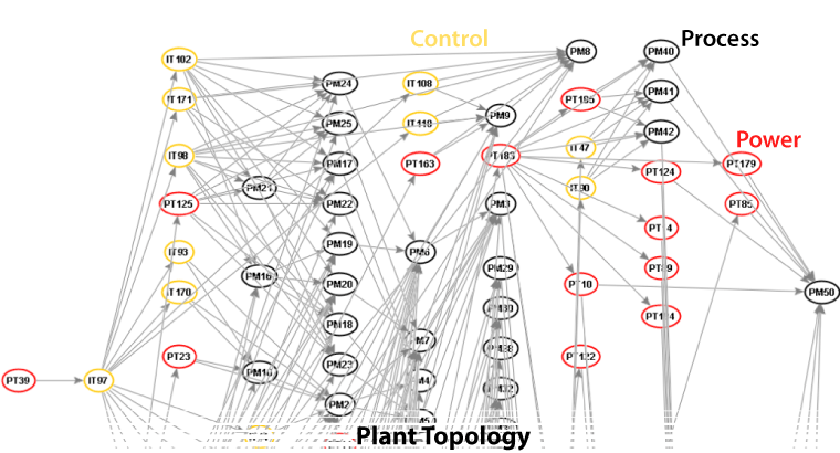
For the desalination megaplant of 250MLD, the graph includes 237 nodes. Navigating directly such a big graph is difficult. For the SFT planning, it is partitioned into sequential subgraphs centered on main process systems like intake pumping stations, pretreatment filters, SWRO units, etc. The subgraph for the intake pumping station is given below.
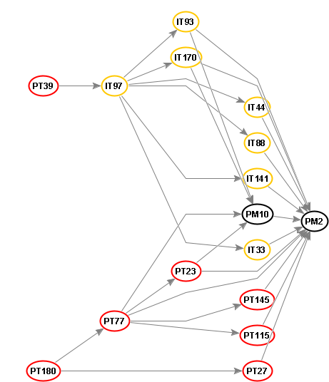
This subgraph represents the following SFT sequence. (The list entry starts with the wiring/system tag and additionally contains a universal identifier used for data storage)
- IU-39: instrument UPS board 204 PT39
- SG-180: power switchgear 266 PT180
- PLC-97: PLC 110 IT97
- DW-27: drive power MCC 257 PT27
- DW-77: drive power MCC 254 PT77
- JBA-44: analog junction box 1 IT44
- JBA-93: analog junction box 2 IT93
- JBD-88: discrete junction box 98 IT88
- JBA-141: analog junction box 3 IT141
- JBD-170: discrete junction box 99 IT170
- JBD-33: discrete junction box 100 IT33
- IW-145: instrument power board 172 PT145
- IW-23: instrument power board 173 PT23
- IW-115: instrument power board 174 PT115
- EM-10: intake chlorination system 411 PM10
- EM-2: seawater intake pumping station 403 PM2
The SFT tasks may be executed by different contractors. To enforce the correct order of execution, crenger.com introduces the SFT broker similar to the one described in “Project Execution and Monitoring”.
When MC is completed, the broker sends an assignee the request to start working on the first SFT node. Later, the assignee may get a request to report the progress online, or expedite the work if the progress is insufficient. After the assignee reports the node SFT completion, the broker sends a request to review and approve the results. Once they are approved, the broker moves to the next node and new requests to assignees.