
Selecting high-level ST as a mainstream of PLC programming standardization leads us to its next milestone - PLC control software architecture (CSA).
We define CSA as a hierarchy of control modules (CM) each one containing other CMs or physical IO devices like valves, switches, meters, variable speed drives, etc. (More details are given in "Instrumentation & Control Systems Design Guide".)
IO devices and CMs represent data structures communicating through events. Events describe the state of CM or the IO device like "ready" or "running" or request (action) like "to start", or "to stop".
Unlike an IO device, any CM has the same set of IO events. As a bare minimum, it includes "collective fault", "not ready", "ready", "to run", "running", "not healthy", "to stop", and "stopping".
Strictly speaking, CM is not necessarily linked to any physical subsystem of the plant. Its main objective is to deduce the output state based on the input and inner states. CM is a state-selecting machine. In that respect, CSA resembles the architecture of neural works used in AI.
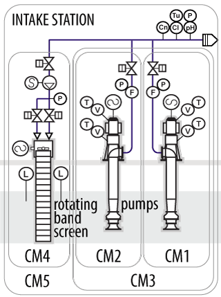
For example, the operation of the intake pumping station with the P&ID shown above may be emulated with CSA including 5 CMs of 3 different types. Type L1 includes only IO devices (CM1, CM2, and CM4), Type L2 - only the L1 modules (CM3), and Type L3 - IO devices, the L1 and the L2 modules (CM5). The L2 module does not contain any IO devices, it describes the parallel operation of identical L1 modules.
On the above P&ID Cn, Tu, Cl, P, pH, F, L, T, and V denote measurement points of conductivity, turbidity, chlorine, pressure, flow, sump water level, temperature, and vibration of rotating equipment bearing houses. All the motors are equipped with variable-frequency drives.
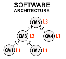 The graph representation of CSA for the intake station is shown to the left. Here arrows depict not only how one structure hides another, but also how the CM state propagates upwards. For example, the intake station is in a "running" state if all CMs are in a "running" state too.
What drastically differentiates CSA from software architectural design applied in the IT industry is its quantitative character. It defines not only the software functionality but the scope of PLC programming. In other words, PLC CSA design shall be a legitimate part of any megaproject offer together with PFD, P&ID, and RBD - reliability block diagram. CSA bears a strong affinity to the latter.
Predictions of the plant operation state and its reliability are governed by the same Math.
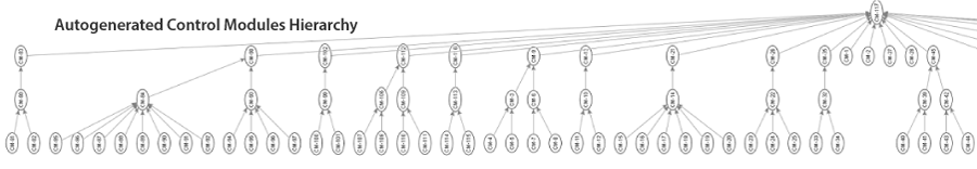
Below are metrics of the CSA case auto-generated by crenger.com from the P&ID of the desalination megaplant with a capacity of 150 MLD. It contains 1932 IO devices, 132 L1-type, 35 L2-type, 25 L2-type modules. In communication, they use 1930 CM-owned events and over 36260 IO-device-owned ones. These mind-blowing figures easily convince anyone that automation of PLC programming is the only choice left.
To translate the CSA design into Structured Text (ST) program one needs building blocks - the full-featured structural components. In the IT world, it is an objective of a software requirements specification (SRS).
Crenger.com suggests the following basic structure types to be declared in the ST program.
- ModuleEvent, (IO device) Event
- SequenceStep, Sequence
- ModuleL1, ModuleL2, ModuleL3
- Meter, Motor, Vsd14, Vsd24, ValveS, ValveI, ValveC
- Pump, Tank
There are two reasons for the introduction of ModuleEvent. Being much simpler than Event, it has a higher level of priority. The finite number of choices makes it ideal for the ST array application. Multiple modules are a consequence of ST's limited capabilities.
The SequenceStep and Sequence structures describe start-up/shutdown operation sequences driven by the same Event and ModuleEvent objects.
As the L1-type modules are intended for parallel operation they contain the "in operation" and "idle" variables. They are needed to even out the operation times of modules switched over between operation and stand-by service. This classic task will be discussed elsewhere.
The "noty" variable is the not-healthy event priority assigned to the module. Often desalination plants are operated with several modules in a not-healthy state. The said parameter handles the situation when enough is enough.
Valves are represented by 3 categories dominating in desalination plants - the hand valve with limit switches, the actuated isolation valve, and the control valve. The Vsd controllability depends upon its size. Its possible range is covered with two types - Vsd14 accepting all the Vsds with an IO count below 14, and Vsd24 with the count above the threshold mentioned.
The final group of structures does not consume or emit events. It is "functions" used for Key Performance Indicator (KPI) and alarm setpoint calculations, or data reporting.
Abridged versions of these structures are described below. (Reporting and error handling are omitted for clarity.)
All of these structures contain the "id" field - an externally auto-generated global unique identifier as the variable tags used in the PLC program are unique only within the plant and cannot be used by the cloud technologies. In addition, Event includes the "oid" field - its owner identifier.
Compared to the old lightweight State, Event contains fields needed for alarm rationalization discussed elsewhere (priority, maturity time, alarm type, hazard level) and code validation (type and implementation). Alarms are discussed in depth in "P&ID Alarm Management".