
The second part of the bootstrapping (BT) template addresses four points of the control logic explained in "Automating Process Control Narrative". They shall be programmed for every control module (CM) of the plant.
- CM states
- IO device alarms
- CM safety interlocks
- CM start/stop sequences
CM states
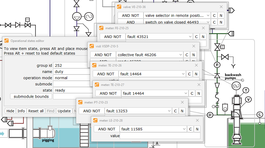
The CM state is defined by a combination of the P&ID item (IO device) events and actions often described by Valve Matrix.
Below is a snapshot of the operational states editor bundled with PlantDesigner. As seen every IO device is linked to the event selector coupled to the Boolean operator (AND, OR, AND NOT, OR NOT) and/or some threshold value. Several events owned by the IO device may be selected and grouped using brackets.
To activate CM State Autodefinition the following sequence of state editing is recommended.
ready -> not ready -> running -> not healthy -> fault
Clustering the IO device events around the CM states is an excellent topic for machine learning and AI.
BT simply converts the data from PlantDesigner to the ST code. Below is an excerpt from an auto-generated code describing the CM-86-RD ("ready") state of the pump's CM shown in the figure above. This state is assigned to true if all the meters and a variable speed drive are not in the "fault" state. Otherwise, the "ready" state is false.
Similar code snippets are generated for all other CM states and all the L1-type modules of the plant. They add over 12000 lines of code.
IO device alarms
PlantDesigner supports the creation of simple, compound, and recipe-based alarms. Here the focus is on simple ones.
Any meter may emit five events - low-low alarm, low alarm, current value, high alarm, and high-high one. The figure below shows how alarms are arranged in PlantDesigner for a flow transmitter. (PlantDesigner sets alarms automatically depending on the type of measurement.)
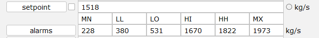
To change the state of an alarm (true or false) the alarm setter function is applied to every CM meter. It iterates through the array of the meter events and compares the current-value event to available alarms. Then the result is assigned to the alarm state. Once alarm states are set, iteration over safety interlocks begins.
CM safety interlocks
A safety interlock - a flavor of the compound event - initiates an Emergency Shutdown (ESD). Its strategies are discussed in "Instrumentation & Control Systems Design Guide".
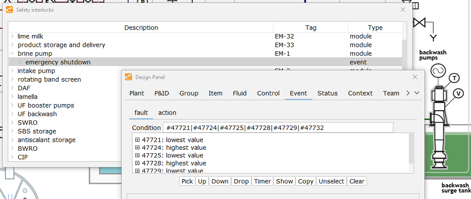
The same principle applies to interlocks - they are imported from PlantDesigner. It offers two ways of interlock definition. Compound interlocks are built with the event editor interface. Interlocks for the pump motors (representing over 90% of all interlocks) are auto-generated. PlantDesigner links the motor shutdown request to all the low-low or high-high alarms generated by the instruments installed on the pump set and its piping.
The figure below shows the auto-generated interlocks list and the event editor with an interlock loaded and ready for editing.
Auto-generation is a preferred way as it covers not only the basic case when
HH -> shutdown
but more sophisticated cases when
(H + H + H) OR (H + H + H + H) OR .. -> shutdown
The latter is often observed in sophisticated systems like the 6 MW high-pressure pump. This masterpiece of engineering with a price approaching US$ 1 million has nearly 30 sensors measuring vibrations and temperatures at different locations. Such types of interlocks can't be programmed manually due to the mind-boggling volume of work. Below are possible combinations for the 2H, 3H, and 4H cases.
C(30,2) = 435C(30,3) = 4060C(30,4) = 27405
The snippet of the ST code for the CM-86 emergency shutdown interlock is given below. As seen the interlock does not change directly the CM state, but alarms do.
CM start/stop sequences
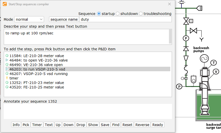
Any operation sequence is a chain of action steps and response steps. A step may be a wrapper around an Event or a timeout. PlantDesigner editor for the operation sequences is shown below. The default normal shut-down sequence is created automatically by reversing the start-up sequence.
ST structures of Sequence and SequenceStep are given in "PLC Software Architecture". Below is the snippet showing the variables declaration and initialization of the CM-86 module.
To execute startup and shutdown sequences two simple functions are used - fcStartup and fcShutdown. The former is given below.
On average, the BT generator for the control logic produces over 10,000 lines of the ST code.