

Designer Guide complements Instrumentation & Control System Design Guide and the PlantDesigner menus description - a quick way to learn about PlantDesigner tasks, scope and produced outputs.
Designer Guide is intended to cover the complete sequence of the plant engineering steps. Some of them are executed by the designer (D), others – by the software (S).
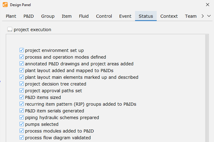
To track the steps execution, use DesignPanel: status.
To anchor the step to the PlantDesigner user interface, the step paragraphs contain links to videos and references to the PlantDesigner menus written as Menu: submenu: submenu.
Any plant engineering starts from some data input. The user shall prepare FEED request using the web site. The request  covers feed water parameters at different months, guaranteed conditions of feed before membranes, guaranteed product quality and capacity, design requirements, commercial data, and others. Then the plant design should be executed using "process definition" and "process design" of the "process" menu.
Before starting your first project we strongly recommend refreshing your knowledge in project engineering and management. The best way to do that is to go through the main documentation types used in process projects.
Steps create an execution sequence. When a step is completed, the software validates it and changes the project status. It may be edited and tracked from PlantDesigner.
Project decision-making tree created (D)
Any project is a collaboration activity. Naturally, setting responsibility scope for any team member is the first task in the project. The dicision-making hierarchy deals not only with delegation of responsibilities in outstanding issues but with the approval and signing off quotations, orders, and invoices. (Main: Users)
Project environment set up (D)
The objective of this step is the PlantDesigner and the project customization. If this step is not completed, the default data will be used. Customization covers process, wiring, procurement, scheduling, and costing.
Process
- Design context (Design Panel: context)
- P&ID logo (Main: logo editor menu)
- P&ID symbols, (Tags: P&ID symbols)
- Object tag algorithms, labels, and structure (Tags: algorithms, labels, components)
- Object selectors (Design : object selectors)
- P&ID items sizing standards and preferences (Design Panel: Item)
- Specifications and guidelines (Files: specification, generic, attached)
- Paint color for equipment (Q&A: paint colors)
Wiring
- Cables database import (Wiring: cables import)
- PLC I/O import(Control: todo)
- Instrument hookup drawings import (Control: instrument hookups)
Procurement & scheduling
- P&ID item cost predictors (Costs: cost predictors)
- Companies (Procurement: companies)
- Agents (Procurement: agents)
- Item lead time predictors (Schedule: lead predictors)
- Schedule activity workload predictors (Schedule: workload predictors)
- Original Equipment Manufacturer (OEM) submittals
Costing
- Costing settings (Design Panel: context)
Design context controls the user access priviliges, design quality (standards, codes, internal procedures), and stores attributes common to all the projects.
PlantDesigner does not set any standards regarding the P&ID symbols graphics. They should be kept simple and understandable to all project stakeholders.
Project logo is a table image. Its cells contain metadata about the drawing and the company logo icon. Once the metadata type is described, the table cell contents are auto-generated directly from a drawing requested.
Project member roles set (D)
Roles are used for checking, approval, and signing off requests for quotation, purchase orders, and invoices.
Operation modes defined (D)
Process operation modes definition is the most critical part of the plant engineering. It's objective is to create parametric envelope for no-minus-tolerance design. Start from adding main operation modes from standard modes library. Go through all the main processes in reverse order and check default capacities of every system. Add all the requested data - standby capacities, installed capacity usage, etc. Then move to chemical dosing. Your final design will be validated against these data.
Plant and RO train layouts created (D)
Using the process operation modes set as an input, the software auto-generates the plant design and initial layout. The user's task is to fine-tune the layout and check the design data.
Annotated P&ID drawings and project areas added (D)
To add P&ID tied to a project area, use Design Panel. To add annotation, use Main: annotation menu. Annotation is inherent part of P&ID. It explains to the project team the subsystem purpose, how it works and design and operational constraints. You may find the annotation samples on the crenger site.
Annotation shall include control philosophy explaining how the subsystem shown on P&ID is operated and controlled with special emphasis on safety logic and interlocks. Control philosophy shall assist control systems engineers in designing the control logic and coding SCADA.
All the P&IDs shall be tied to the project subareas. Default areas are intake and pretreatment, SWRO units, BWRO units, posttreatment. Areas are critical for concurrent engineering, procurement, wiring, and commissioning. In these steps big percentage of relevant data is auto-generated by PlantDesigner.
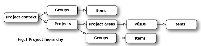 Project Hierarchy
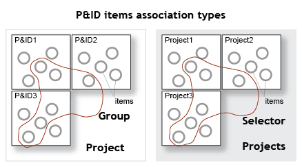 Project selectors and groups
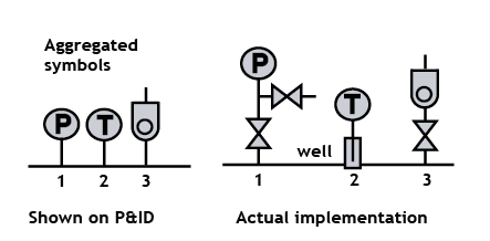 P&ID aggregated symbols example
 Project approval paths set(D)
This step deals with the project resources allocation and the project approval sequences. They should be set for engineering, procurement, the time schedule tracking, and files (Users: approvals editor).
This data is the basis for engineering information approval management by PlantDesigner. If approval is not done, transition to successive step is blocked automatically.
P&ID items sized and recurring item patterns added (D)
The P&ID items sizing is the biggest step. It uses the P&ID item tab and Fluid tab of Design Panel.
First define the fluid properties by selecting the fluid type in the upper left corner menu. The fluid data may be entered manually, copied from another P&ID item, ot auto-generated. After this click the P&ID item tab. In the upper left corner menu select the item type and then press reset.
Normally the reset means returning the dialog state to the beginning or no-data state. As process engineering does not have no-data or void state (it is always replaced with intuitive assumptions), PlantDesigner treats reset as a moment for voicing some auto-generated engineering solution deduced from the project context. This solution is called auto-completion.
The auto-completion term is also used to denote auto-generation of the equipment pieces usually accompanying the main P&ID item. For example, the pump scope usually includes discharge piping, isolation valve, non-return valve, flowmeter, air-release valve, etc. To add these items to P&ID, the user needs to select the proper entries in the "instrumentation" list.
This set of items is called Recurring Design Pattern. It is described by so-called good engineering practice rules and industry practices. Crenger.com contains a rich collection of RDP blocks.
If the meter is the source of low-low, low, high or high-high alarms, they shall be entered at this step. Instrumentation stored properties shall be extended to alarm deadbands, scan rates, process safety times and data acquisition directives.
To complete sizing, the P&ID items shall be linked. Any meter or valve shall be linked to its container: piping, tank, pump. Ditto for motors and variable speed drives. PlantDesginer uses linking to auto-size dependent P&ID items like flowmeters, valves, motors, driver, etc.
The basis for pressurized item sizing is the fluid parameters like pressure, temperature flowrate, salinity, etc. Collectively, they denote the fluid node. In other words the item sizing is rooted into a collection of interrelated fluid nodes – a snapshot of the plant real operation. PlantDesigner allows working with many snapshots. They may serve different purposes – normal and abnormal duties, minimum and maximum loads. The basic snapshot is for Mechanical Design (MD snapshot).
These snapshots bear some resemblance to the tabulated data on the main process parameters depicted on the process flow diagram (PFD).
Recurring item patterns group (RIP) is a cornerstone concept of PlantDesigner. It is a compact representation of the P&ID items group which otherwise be replicated more than once on the P&ID. This concept has been suggested by the ISA standard many years ago to make P&ID more readable, but never implemented by smart P&ID software. The second reason behind the RIP introduction is the plant reliability analysis. The unique feature of RIP is that it may be 100% reliable.
RIP is a building block of the process module with predictable reliability and the production rate. Even if RIP is expanded on the P&ID, PlantDesigner treats it as true RIP.
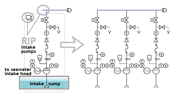 P&ID and RIP
 After this step PlantDesigner auto-selects pumps using their specifications and the pump database containing over 120 models. The user may select the pumps manually using the pump selector interfaces of PlantDesigner or that of the web site. The same interface may be used to adding new pumps using the curve reader application.
Use Design: pump viewer
Use Design: pump selector
Finally, the plant hydraulic profile is added. Hydraulic profile (HP) is a bar chart showing the fluid level variation in open tanks of the plant. Its objective is to help the designer make correct assumptions about the hydraulic losses in the piping with gravitational flow regimes.
The HP chart is auto-generated by PlantDesigner from the tank specifications. It additionally adds the RO membranes arrays heights as they are important in sizing the suck-back tank geometry.
Use Design: Tanks and vessels: hydraulic profile
Piping hydraulic schemes prepared (D)
The user may select between "fast" and "detailed" calculations. To execute fast option, the user draws the line crossing the P&ID items of interest. Crenger does the rest without isometrics.
For detailed option the isometrics sketch shall be prepared. The user builds a sequence of hydraulic resistances with varying flowrates. It may include the pump and be chained to another sequence. This sequence may be merged with PU calculator as well to build so-called "installed pump characteristics".
Vessels and tanks nozzles sized (D)
This step completes the tanks and vessels sizing. Its objective is to size and locate nozzles and link them to P&ID items. Linking allows automatic update of nozzle if the owner item is changed.
Use Design: Tanks and vessels: nozzles
P&ID item serials and alarms generated (S)
P&ID item is an abstraction denoting some real piece of equipment. Item in the RIP group denotes a number of identical pieces. These pieces are called Serials as for each piece there exists a unique serial number. In turn, Serials denote real products to be procured. So all the P&ID item properties are automatically replicated in Serials. While item belongs to P&ID, Serial belongs to Layout.
From the control point of view, any wired P&ID item (WI) is a source of events and states. They make WI remotely visible. WIs include limit and proximity switches, instruments, valves and electrical drives. All of them have different sets of states and events. For example, flow meter has abnormal "Fault" state described by digital input and normal "Value" state described by the analog input. DOL‐started motor has much more individual states and events – Start/Stop, Fault, Running, Field Ready, Start From Field, MCC Ready and others.
PlantDesigner has generic database of equipment type states and events. It is used to auto-generate states and events for each WI and cable terminals (MCC, and switchgear).
Alarms selected during the items sizing are turned by PlantDesigner into "soft-wired" events automatically.
P&ID items and groups mapped to plant layout (D)
Mapping is used for auto-wiring of the plant and auto-generation of the noise map. Not all items are needed mapping. To define which to map, use the popup menu and "Not mapped" submenu. PlantDesigner auto-selects the items to be mapped. To make mapping faster for RIP groups, use copy-paste menus.
Noise map is a layout with the noise sources located. Unlike the first, sound pressure map is responsive: it shows the noise levels on screen at the mouse pointer location.
PlantDesigner auto-generates the sound pressure map for pumps, motors, energy recovery devices, air blowers and other equipment that is already mapped to layout.
The sound pressure map is a quick way to understands whether the noise abatement shall be in-built into the design (and added to specification) or not.
Plant underdrain system mapped to layout and sized (D,S)
Underdrain piping is used to avoid the plant flooding. It may be a result of abnormal operation or abrupt overflow piping, rupture discs and pressure relief valves. Underdrain design includes piping sizing, layout, and costs unplanned shutdown of some system. Underdrain shall accept full flowrate from special P&ID items:.
Process modules added to P&ID (D)
Robust control design necessarily includes the plant partitioning into modules which may run independent of the successive modules. Process module (PM) is a group of P&ID items with a single well-defined global function or purpose. The last is described by a verb, like to pump, to filter, to chlorinate, etc. By definition, PM is a node on the Process Flow Diagram, Reliability Block Diagram, Commissioning Schedule, and the Plant Control Diagram.
As a control node, PM is described by a set of states and events: Collective Fault, Not Ready, Ready, Starting, Not Healthy, Running, Autorun, Shutting down.
The Running, Ready, and Not Ready states are reversible: transitions between them are controllable. The Fault state is abnormal and risk associated one. Any transition to it is unidirectional and irreversible. Depending on the module purpose, even if it is in the Fault state, the Plant may be considered Healthy.
The Not Ready state means that PM is not available for requested task but it may be in higher level state (Ready or Running) for other task. All PM actions are finite‐time transitions. For example, the dual‐media filter has 3 main modes: Duty, Backwash and Air scouring. It is simultaneously in Running state for backwash and Not Ready state for main filtering process.
All PM groups shall be linked. Linking reflects the process sequencing and is used for PFD auto-generation, the plant states and events definition, and for reliability prediction.
linking PM groups begins from the last PM group. Open the group in the design panel and click the conmark button to turn PM into container. Open the child PM group and tick "link to container" option.
Process module functional states registered (D)
This step objective is to link the process modules states to a combination of the wired item states and events. For example, the process module is considered in the Running state if all the drives are in running state too.
The process modules main states are Fault, Not Ready, Ready, Not Healthy, Running. To use PlantDesigner auto-generation algorithms, add states in the following order: Fault, Ready, Not Ready, Runnning, Not Healthy.
If the process module has a number of operating modes, states shall be created for each mode. Example is multi-media filtration, ultrafiltration, reverse osmosis. These processes are periodically interrupted with backwashing or CIP.
If process module includes manually operated subsystems, they may be excluded from the task by defining the polygon area for states. Typical example is CIP subsystem. It may include auxiliary subsystems used for preparing CIP cleaning fluid before actual CIP.
Use Control: module states: edit.
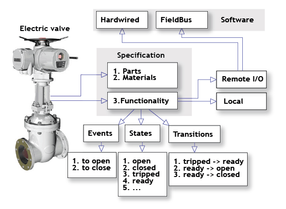 P&Id item specification and functionality
 Drive safety interlocks registered (S)
Interlock describes a system response requirement to predetermined conditions caused by the system malfunctioning (safety interlock) or the process sequencing (process interlock).
Interlock may initiate the timed action as well. Safety interlocks usually initiate the plant or the module shutdown. It may have a number of steps including closing valves, stopping auxiliary systems, motors, etc.
PlantDesigner auto-generates safety interlocks for pumps by connecting all the LL or HH alarms generated by the instruments installed on the pump, its motor, and discharge piping to the drive shutdown event. This compound interlock may be edited by using the Event tab of the Design Panel.
PlantDesigner allows building compound, sequential interlocks of any complexity by using the Boolean math.
Process module dependencies added
The module dependencies are part of start/stop sequences: they define their preconditions. For example, SWRO unit cannot be started without pretreatment system in operation. Dependencies are defined only for interlinked process modules.
PFD and RBD created and validated (S,D)
To auto-generate PFD, use Control: PFD menu. PlantDesigner validates data and if problem found, the errors list is shown.The user may edit the PFD layout to make it more readable and compact.
To auto-generate RBD, use Control: RBD menu. PlantDesigner validates RIP and expanded RIP data and if problem found, the errors list is generated.The user may edit the RBD layout to make it more readable and compact.
PlantDesigner uses RBD and the default reliability database to auto-generate the reliability data for process modules and the plant for loads ranging 100% to 50%.
Alarms priority and suppression set (D)
Alarms prioritization and suppression are a critical point in control design; it becomes object-oriented and more understandable. To create priority groups, select Control menu and click Alarms suppression. The same-level alarm with lower probability shall have higher priority. Example is bearing temperature and vibration. Comparing to the former, the latter is by far more common.
The suppression tree includes the alarms with the same meaning, like high flow rate and VSD high load as the latter is consequence of the former. To add the alarm to suppression tree, select the row and click Add button.
Control loops created (D)
To create the control loop, the user shall enter the following: short description, control type, control parameter, controller type, transfer function type, redundancy, hazard level, induced losses, trigger alarm, control objective, signal (error) sources, final control elements.
To add control loops, use Control: control loop.
Process module start/stop sequences added
Start/Stop sequences are the last validation of the plant design compliance with the project functional requirements regarding the process module automation levels. Sequences show whether they are fully-automated, or semi-automated.
Usually sequences are followed by P&ID item multiple updates. Manual valves are replaced with actuated ones, additional meters are added.
PlantDesigner offers simple tool for the operation sequences development which is rooted into the following protocol. Operation sequence is considered a chain of the action steps and response steps. An action step is an unordered collection of actions like ‘to open a valve’ or ‘to start a motor’. By analogy the response step is an unordered collection of responses such as ‘valve is open’ or ‘motor is running’. Inside the step the order of items – actions or responses are irrelevant: swapping items produces the same result.
The process module Ready state is precondition for startup sequence. If the process module is linked to other modules, its Ready state depends upon the state of neighboring process modules.
Nearly every start-up sequence shall end up with control loop activation. To create normal shut-down sequence just click the @quot;Reverse@quot; button.
Use Control: sequences: edit
Plant data acquisition updated
The primary task of the data acquisition is classification of the outputs collected from the plant instruments. Signals may be used for safeguarding, control or the performance monitoring. In the plant control hierarchy with 3-levels, the signal visibility may have the following options: local, process module, operating module, and plant. In addition different destinations (database, HMI display, messaging, web, reporting) may be set. Signals may be transformed by the so-called transfer functions.
Transfer functions are a backbone of Any Data Acquisition System defined by PlantDesigner. They are used for the algorithm-driven alarm creation, for the creation of the operation and maintenance report templates, and for description of signals propagation up the control hierarchy.
Use Control: Data acquisition and Function editor.
PLC and MCC groups created and mapped to plant layout (D)
PLC and MCC groups contain Serials (not P&ID items!) that shall be wired to PLC or MCC accordingly. To group serials, the user shall select polygon area on the layout. All the serials inside the polygon will be grouped automatically. These groups shall have the same description – "all".
PlantDesigner analyzes the power consumers. If they have different voltage, PlantDesigner automatically creates additional MCC groups and moves serials to the proper voltage group.
Auto-wiring executed (S,D)
The user task is to select the proper location of junction boxes, PLC cabinets, electric panels, MCCs, and switchgear after auto-wiring has been done.
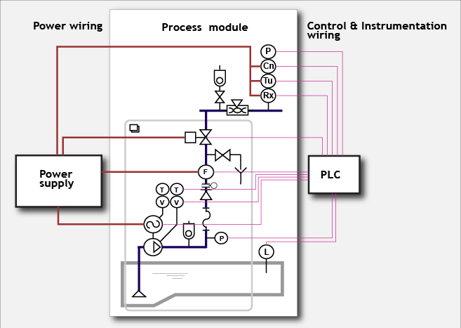 From P&ID items to wiring
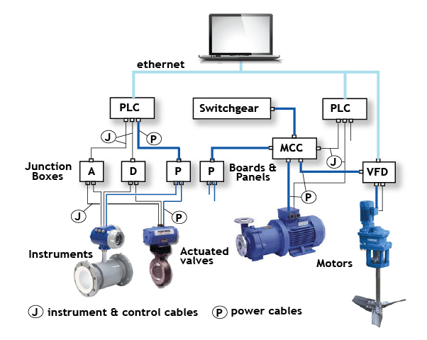 Wiring principle scheme
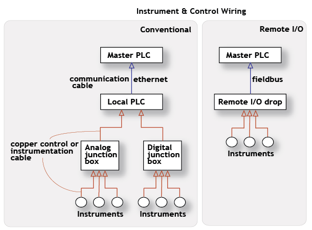 Instrument and control wiring
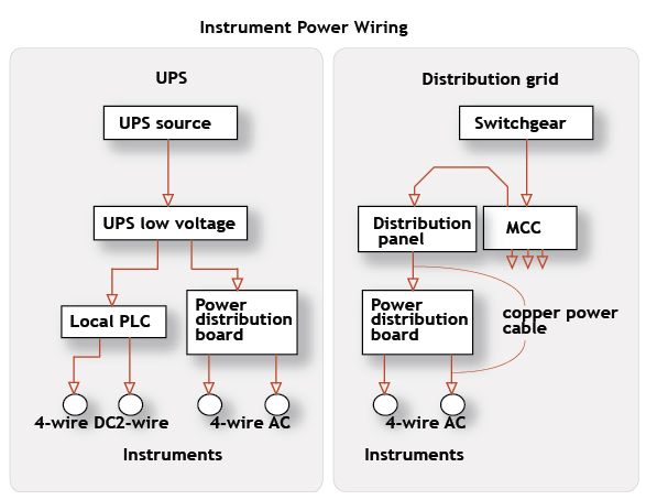 Instrument power wiring
 Drive power and instrument wiring
 Cables and glands, transformers, and PLC IO modules auto-selected and BOM generated (S)
After auto-wiring PlantDesigner auto-selects cable types and the cable glands from the database and creates Bill Of Quantities (BOQ). In addition, it sizes transformers.
PlantDesigner selects the number of PLC I/O cards and the card racks capacities. It connects instrumentation and control cables to cards and creates PLC addresses. The viewer allows navigating the P&ID items, cables, card and racks.
One-line electrical diagram validated (S, D)
The plant one-line electrical diagram is auto-generated from wiring diagram, focus being on the capacity ratings of MCC, power boards and panels. Before this PlantDesigner validates the existing wiring completeness.
Instruments attached to hookup drawings (D)
PlantDesigner moves all the information about the hookup items (tubing, elbows, connectors, etc.) from hookup drawing to database. This information may refer to the assembly and manufacturing drawings, the manufacturer catalog datasheets and the project specification of instrumentation and shall be verified before submitting the hookup drawings to the subcontractor. By the author estimate, about 50% of all the 'as-made' hookup drawings (already used more than once) contain errors or misprints.
PlantDesigner not only auto‐generates the hookup BOM (bill of materials) and the hookup specifications with all relevant information on demand, but also checks the applicability of the hookup drawing to the specific instrument, the fluid conditions and the materials.
Equipment acceptance, commissioning, and maintenance checkpoints registered (D)
Equipment inspections and tests number and approval procedures shall be selected based on the available resources allocated to Quality Assurance and Control. Test witnessing and approval points bear heavy impact on the project schedule.
In this step the designer selects inspections and tests for equipment groups described by the special selectors. They, in turn, project all the inspections and tests onto the P&ID items and serials.
To remove the test, just uncheck it. To add the a number of tests, select them all, click Drop button to remove not selected, and press Apply button.
Generation of commissioning checkpoints is based on identical procedure. The designer selects the check points from the available list, attaches them to special selectors (or uses the default attachment). Later they create empty check records for all serials. While the checkpoint count is below 2000 the check records number may be well above 50 thousand. To view the commissioning checks status menu, press Alt and right mouse button.
PlantDesigner auto-generates the preventive maintenance tasks for each Serial with activation date to be set later. The total number of such tasks is usually well above 1000.
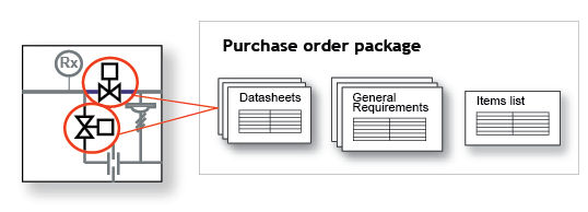
Equipment pieces, parts and instruments grouped for procurement (S,D)
Once the equipment pieces and the instruments have been specified, they shall be grouped into procurement packages. Grouping takes into account the pieces similarity (equipment class, size) and the Original Equipment Manufacturer (OEM) range of products. Grouping is a three-step process. PlantDesigner creates default packages using the patterns already recorded in database from the previous projects. After this the user may merge some packages according to her/his expertise. Thirdly, PlantDesigner gives hints regarding which packages are desirable to split due to differences in the lead time. Finally PlantDesigner check the eligible OEMs and if the quantity is less than three, signals the alarm.
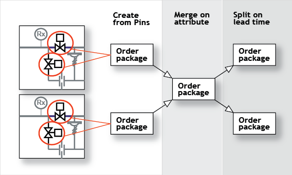 Order packages aggregation principles
 Here the user may add item supply groups and functional supply groups to P&IDs and planned procurement packages. Normally they contains similar items like pumps, valves, metering pumps, etc. Item supply group contains dissimilar items logically related like pump and discharge manifold with pressure transmitter and isolated valve installed.
Functional supply group is intended for procurement of well-defined functionality, implementation details are not essential. An example is pre-packaged chemical dosing systems.
Equipment vendor submittals registered (D,S)
Every purchased piece of equipment is accompanied with a number of documents reflecting main steps of the equipment manufacturing and testing. Usually they are grouped into Manufacturer's Record Book (MRB). Editor links the generic submittal types to P&ID item selectors. They do the rest. The user may remove existing documents from or add new documents to submittals.
Use Files: OEM submittals
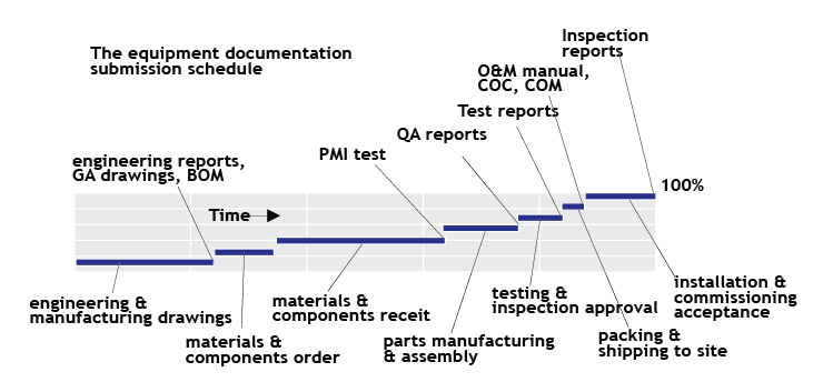 equipment documentation submission schedule
 Equipment and instrumentation order packages optimized (S,D)
Optimization objective is to obtain as much quotations as possible. So packages should be customized to the current original equipment manufacturers' range of products. Optimization includes two methods: merging packages and splitting packages on lead time
Payment schemes attached to order packages (S,D)
Once the purchase order packages having been assembled, they shall be linked to preferred payment scheme. It is conditional: every step payment is conditioned by the manufacturing schedule stage results. User may select already pre-built schemes or create a new one. Linking ranges from manual to automatic. The latter uses the patterns from the previous projects.
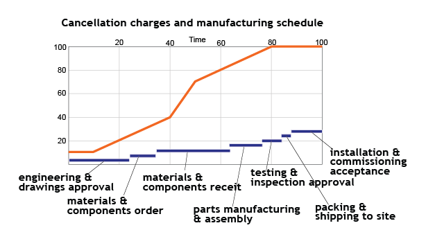 Manufacturing schedule, payments and cancellation charges
 Specifications and files attached to order packages(S,D)
Assembled purchase order packages may be linked to specifications describing general requirements for the equipment class. User may add new specification or edit the existing one with the web application. Linking ranges from manual to automatic. The latter uses the patterns from the previous projects.
Besides specifications and scopes of work, sometimes the files showing the general arrangement, sketches or dimensional drawings (like isometrics) are attached.
 Order packages documentation attachment
 Spare parts and items stock created (S)
One should differentiate between the spare P&ID item and spare part for P&ID item. The former is defined by the plant designer, the latter – predominantly by OEM. The spare items selection algorithms are based on the good engineering rules, lead times and approximate MTBF values.
The algorithms address the worst case scenario when the plant is maintained by the O&M company not sharing resources and stocks with other plants.
Project schedule generated (D,S)
When the user click the "New project" menu, PlantDesigner starts data validation. Once it is done and no inconsistencies found, the user is suggested to review the input data. It includes the following.
- Selecting main contractor and its scope of work
- Selecting subcontractors and their scopes of work
- Selecting project managers and their scopes of work
- Defining resources quantity for each engineering discipline
- Reviewing and updating the sequence of the equipment ordering in each lead time group
- Reviewing and updating the sequence of process modules commissioning
- Reviewing and updating the extended scope of work
PlantDesigner generates graph of activities; it is used for generation of Gantt charts for the following cases: all activities (L1), work packs (L2), all commissioning activities (LC1), all commissioning work packs (LC2), and order packages.
Some activities contain the document names to be submitted at the end of activity. The approval of the document may be required or not depending on the activity context.
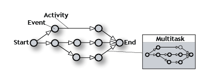 Schedule graph explanation
 Project costs generated (S)
To view the project costs summary and the pie chart, use Costs: budget, pie chart, order costs
Project submittals packs generated (S)
Project submittals packs contain all the project data and information scoped for handover. It may include specifications and datasheets, MRBs, compliance certificates, construction and inspection certificates, operations and maintenance manuals, as-built documentation, etc.
PlantDesigner groups submittals into packs and creates submission schedule and metrics.
Plant commissioning check records generated (S)
Check record contains results of generic check point applied to similar equipment.
Order packages exported (S)
Before this step the order packages are already linked to payment schemes, specifications and technical attachments. Now commercial documents are added: confidentiality agreement, purchasing terms and conditions, the bill of quantities, the order summary, and the request-for-quotation letter. The order packages are zipped and placed into the plants directory. All these packages may be accessed by OEM via the web site.
Bidding reports generated (D,S)
Bidding documents include project technical offer, commercial offer, operation sequences, reliability analysis, executive summary, and HAZOP analysis. The task of the designer is to compose these documents from auto-generated parts.